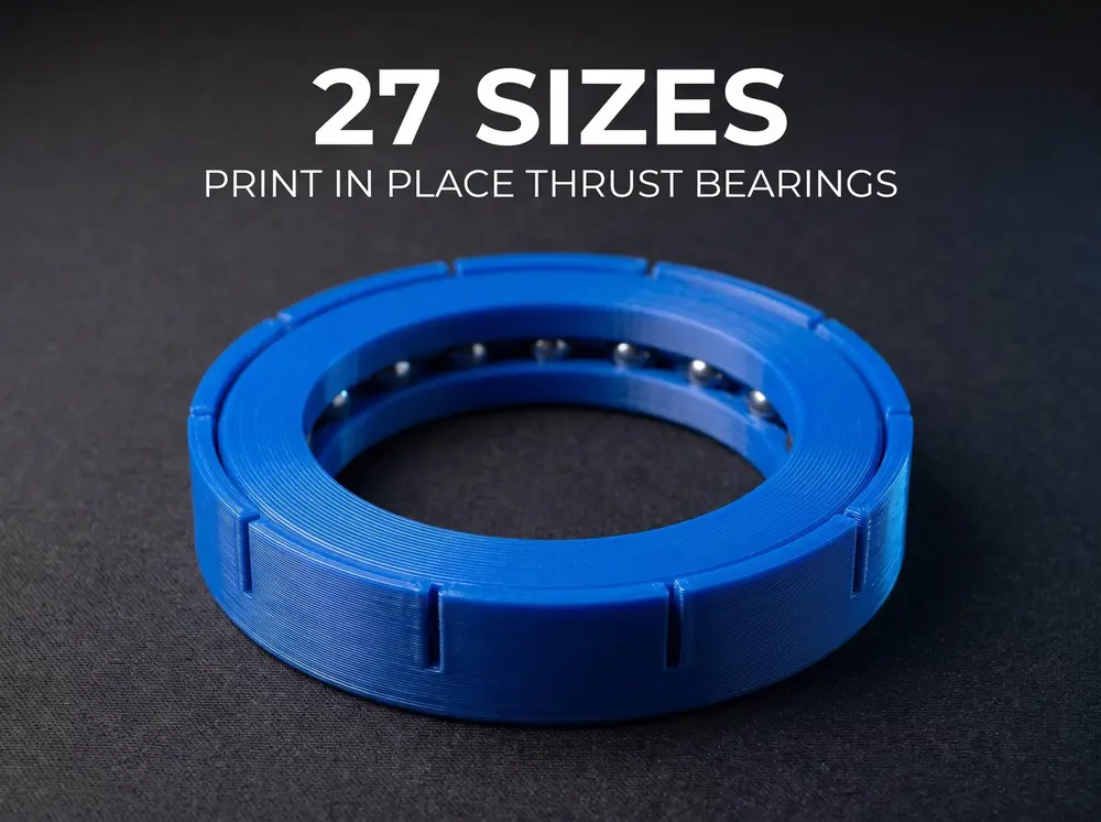
Thrust Ball Bearings PiP | 27 Sizes 51200 51300


Print in Place Thrust Bearings | 27 Sizes
Axial load, printed flat, snapped together in one second.
The companion set to my radial bearings. These take the load your deep groove bearings cannot: pure axial thrust. ISO 104 standard envelopes, from a 10 mm bore up to 50 mm.
Two pieces, zero supports
Each bearing prints as two parts:
- Part A · the lower washer, with the raceway, the snap rim and all the balls already in place
- Part B · the upper washer, printed upside down so its groove faces up
Both parts lie flat on the plate. Neither needs a single support. Press B into A until the rim clicks over it, and it spins.
The balls start on the plate
On a radial bearing the balls sit mid air and the printer has to bridge into nothing for over a millimetre. Here the raceway is concave and faces up, so every ball begins 0.15 mm above the groove, which is less than one layer.
No floating islands. That is the whole reason this design exists.
Verified, not estimated
Every one of the 27 sizes was measured solid to solid in CAD:
- Ball to race clearance: 0.150 mm on all 27
- Interference on any model: none
- Snap rim strain: 0.24 to 1.83 percent, below the point where PLA cracks
That last number matters. A continuous 1.6 mm rim would have to stretch 3.8 percent to let the upper washer through, and PLA fails between 2 and 3. So the rim is split into six, eight or ten fingers depending on diameter. Each finger bends as a cantilever instead of the ring pulling as a hoop. The finger count and the lip height are calculated per size, not copied across.
What is included
Series 51100 · light
51100 · 10 × 24 × 9 · 15 balls 51101 · 12 × 26 × 9 · 17 balls 51102 · 15 × 28 × 9 · 23 balls 51103 · 17 × 30 × 9 · 25 balls 51104 · 20 × 35 × 10 · 22 balls 51105 · 25 × 42 × 11 · 21 balls 51106 · 30 × 47 × 11 · 24 balls 51107 · 35 × 52 × 12 · 27 balls 51108 · 40 × 60 × 13 · 24 balls 51109 · 45 × 65 × 14 · 26 balls 51110 · 50 × 70 × 14 · 28 balls
Series 51200 · medium
51200 · 10 × 26 × 11 · 12 balls 51201 · 12 × 28 × 11 · 14 balls 51202 · 15 × 32 × 12 · 14 balls 51203 · 17 × 35 × 12 · 15 balls 51204 · 20 × 40 × 14 · 14 balls 51205 · 25 × 47 × 15 · 15 balls 51206 · 30 × 52 × 16 · 17 balls 51207 · 35 × 62 × 18 · 15 balls 51208 · 40 × 68 × 19 · 16 balls
Series 51300 · heavy
51305 · 25 × 52 × 18 · 12 balls 51306 · 30 × 60 × 21 · 12 balls 51307 · 35 × 68 × 24 · 12 balls 51308 · 40 × 78 × 26 · 11 balls
Series 51400 · extra heavy
51405 · 25 × 60 × 24 · 9 balls 51406 · 30 × 70 × 28 · 9 balls 51407 · 35 × 80 × 32 · 9 balls
Print settings
- Supports · none, on either part
- Layer height · 0.16 mm, drop to 0.12 mm for the 51100 to 51103
- Nozzle · 0.4 mm
- Walls · 3
- Infill · 25 percent
- Ironing · off, it welds the balls to the race
- Elephant foot compensation · 0.15 mm
- Orientation · part A as supplied, part B flipped groove up
Four things that decide whether it spins
1. Flip part B. Its groove is concave. Printed the wrong way up it becomes a dome over thin air and the raceway is ruined. Flipped, it has no overhang at all.
2. Calibrate your flow. The gap is 0.15 mm. Five percent of over extrusion closes it and part A comes off the plate as a solid disc.
3. Press, do not force. Line B up flat, press evenly with your thumbs, and the fingers click over it. If it will not go, the fingers are fused to each other at the slot: run a knife down each slot first.
4. Break it in. Twist firmly a few times before loading it. It frees up quickly.
Material
PLA for stiffness and clean separation. PETG runs smoother once freed but strings into the raceways. ABS and ASA shrink into the clearance.